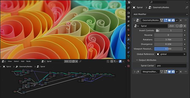
If you've ever wanted to learn Blender's Geometry Nodes system, this article will give you a great starting point so you can make even better Hubs scenes.
Time to dive into some leaves! This tends to be one of the more elusive parts of creating 3d trees. As I mentioned in Part 1, since a lot of creators lean toward using 3rd-party tree solutions, they simply use whatever method the add-on does to make leaves and then… leave them alone. However, the leaves that tree add-ons usually produce are often not suitable for use in real-time applications like Hubs that have stricter limits on polygons and textures. Fortunately, with a little knowledge of Blender’s Geometry Nodes system, we can make leaves pretty easily. Not only that, we can even make our own adjustable parameters–almost like we developed our very own tree system.
Geometry Nodes - An Overview
If you’re a Blender user, you’ve probably seen lots of videos cropping up around the topic of Blender’s Geometry Nodes. Well, if you’ve kept telling yourself that you should get around to learning about them, now is a great time. Having a goal in mind makes learning this system much easier.
Geometry nodes work similarly to the nodes you’ve probably used in places like the Shader Editor. Instead of using a flowchart of nodes to define the look of a particular material, Geometry Nodes allow you to treat the mesh of your object(s) in a similar fashion. Each node does a particular function that can be chained together with other nodes that further alter things about the object. The nodes are designed to do very specific things–often small operations like moving some vertices around randomly or duplicating a face–kind of like how modifiers work, except on a much finer level.
We’ll be using Geometry Nodes to scatter leaves across the surface of our tree canopy. We’ll add some simple controls for adjusting things like leaf rotations and scale, but you’ll be able to make your own parameters once you understand the basics.
The Setup
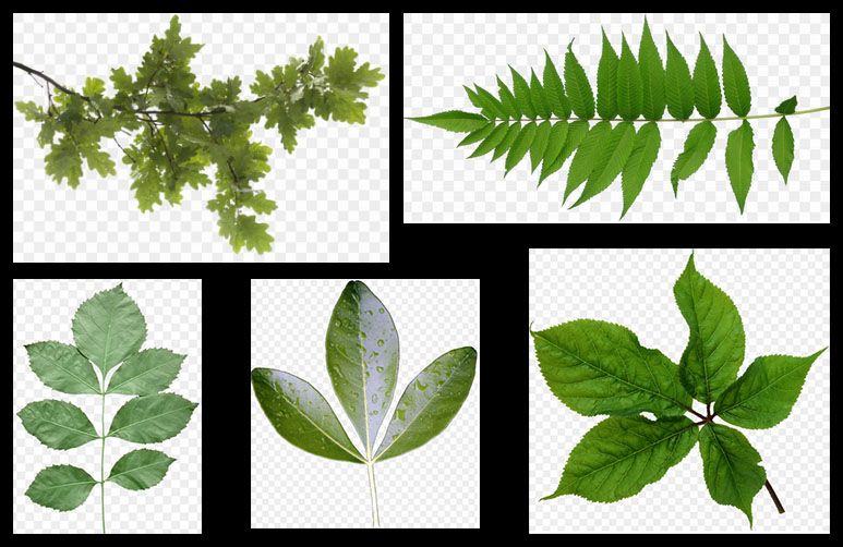
First, we need to start with a mesh object–in our case, we can use the canopy mesh we made in Part 1. Next, we’ll need to make a single leaf object. For the sake of simplicity, we can use a plane, but I like to make something with a sense of direction. In other words, I like to know where the stem of the leaf should be as well as knowing which side of the leaf I’m looking at. Of course, the type of plant or tree you’re making will ultimately determine what it should look like.
I usually start with a plane, scale its vertices down until it’s about ‘leaf-size’ relative to the canopy, then add any additional geometry I might want to shape the plane into something more leaf-like. This leaf is best created at the origin (0,0,0). We can add a texture if we want, but this entire leaf can be adjusted later–even at the end. That’s part of the beauty of a procedural system like Geometry Nodes.
Geometry Nodes - Your First Graph
Now we will select our tree canopy mesh and put a ‘Geometry Nodes’ modifier on it. Because it’s a modifier, you can think of this whole graph we’ll create as the inner workings of a custom modifier designed by you.
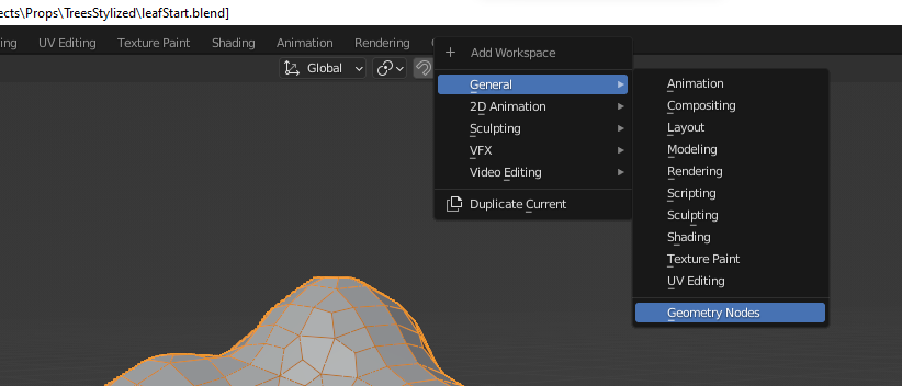
To begin editing the Geometry Nodes graph, we need to open up a new kind of Blender Workspace. At the top of Blender, click the small tab with the plus (+) sign and choose ‘General’-->’Geometry Nodes’. You’ll get a new view that gets you ready for editing.
By default, there’s not much to look at. Just two nodes–an input and output with nothing in between. That means the graph currently does nothing to the mesh. But just like a material graph, inserting things in the middle is what affects the object to change.
Rather than aimlessly trying out nodes (which will likely have mixed results when you don’t know how they work), we’re going to get our leaf object scattered across the surface.
First, we’ll add a node called ‘Distribute Points on Faces’. I’m not going to show every node being added, but be aware you can use ‘Shift+a’ to bring up a pop up menu to add nodes. You can also make use of the ‘Search’ function to find nodes much faster and avoid all the sub-menus.
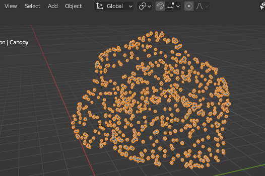
This node scatters a bunch of points all over the surface of the mesh. In doing so, the graph now sees that node as the last operation. Since that operation replaces the mesh itself, the surface geometry disappears. (Don’t worry, it’s still there.)
When you add a new node, it’s a good idea to see what it can do. ‘Distribute Points On Faces’ has some options to explore, including the dropdown for the method for how it scatters points. ‘Random’ is just that–random. It has no concern for how close together the points get. Using ‘Poisson Disk’ gives you options for how closely the points can be placed. Refer to the Blender manual if you want to learn about any node in more detail.
Let’s get those little points turned into our actual leaf object. We need to add another node called ‘Instance on Points’. This one will go after the first node. When everything disappears after adding it, don’t panic, (which is generally good advice when making 3d art).
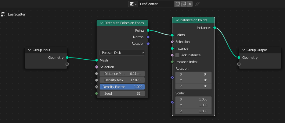
‘Instance on Points’ does exactly what its name says: It takes some instance of an object and puts one on every vertex (aka point) of some other thing. (It’s worth noting here that ‘vertex’ and ‘point’ will be used interchangeably in Geometry Nodes.) But we haven’t told it which object yet so it kind of breaks things until we keep going.
Adding the leaf object is really easy. You can simply drag/drop it from the Outliner right into the Geometry Nodes graph. This will automatically produce an ‘Object Info’ node with the leaf object already listed in it. Then we connect its ‘Geometry’ output to the ‘Instance’ input of the ‘Instance on Points’ node we just made.
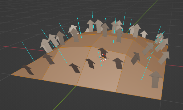
As soon as our leaf object is hooked up to the graph, we instantly see it scattered across the canopy surface. The thing is, every leaf object is facing the same direction.
Fortunately, there’s a node that will make each leaf get its direction from the faces of the canopy. It’s called ‘Align Euler to Vector’ and it belongs in the graph like so:
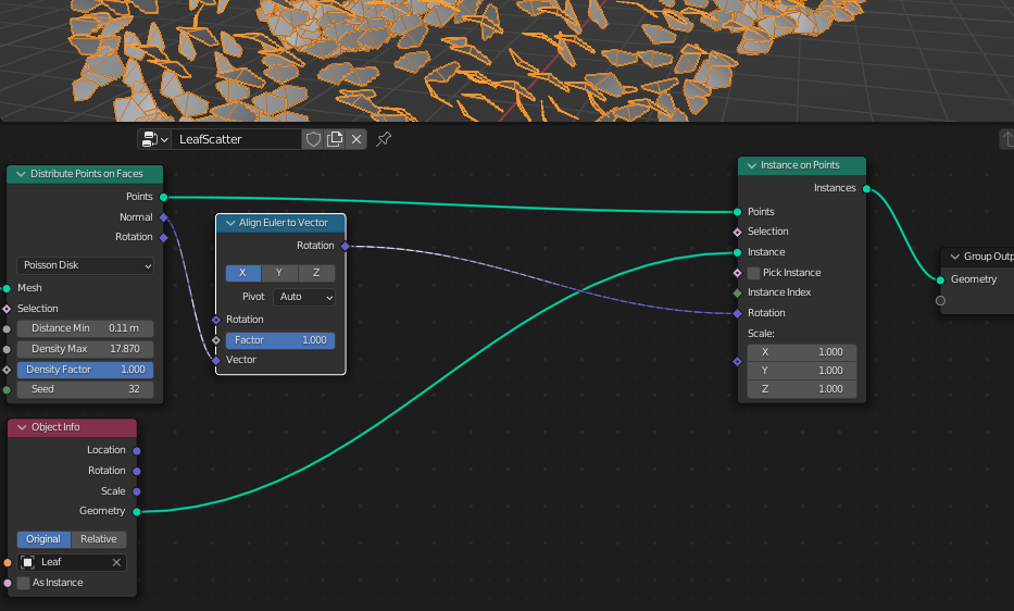
What’s happening here is the ‘Align’ node is taking the normal direction of each face of the canopy mesh and passing that information along to the ‘Instance’ node’s ‘Rotation’. That way, when a leaf is being placed on a face of the canopy, it gets rotated based on whichever way that particular face of the canopy is oriented.
Now, the way your leaves are facing is partially dependent on how you modeled them. When I made my initial leaf, I had it pointed toward the positive Y (+Y) direction. So for me, I need to toggle the ‘Y’ axis on the ‘Align’ node. Another important factor is where your single leaf model’s local pivot point (origin) is located. I’m going to go back and move the leaf’s pivot so it’s right where the stem would be. This helps you start to understand why we often model things around the world origin (0, 0, 0).
Last, you may want to play around with the ‘Pivot’ parameter. For my model, I found that setting it to ‘Z’ gave me the best-looking results. But remember, you can always go back and mess with these things later.
Geometry Nodes - Adding randomness
If you made it this far, you now have a graph that’s almost done. It would be nice, however, to introduce a bit of randomness to each leaf so they’re not all identical in size and relative rotation.
This is something you could go back and add later if you want, but I recommend trying it out now while you still remember what everything in your graph does.
Random Scale
An easy one to start with is the scale of each leaf. We can plug a ‘Random Value’ node into the ‘Scale’ input of the ‘Instance on Points’ node. Then we’ll set a ‘Min’ and ‘Max’ value so that each leaf gets randomly scaled slightly bigger or smaller than the default (1). Values like `0.8` and `1.2`, respectively, will make them range anywhere between 20% larger or smaller, for example.
Random Rotation
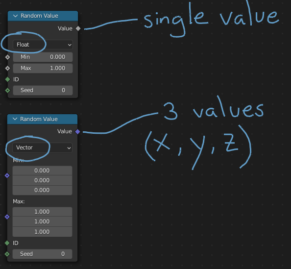
Since we’re dealing with 3-dimensional rotation, we’ll need more than a single random value. Instead, we can change a ‘Random Value’ node to use a vector. Yes, things get a little ‘mathy’ here, but bear with me. When you switch the node to ‘Vector’, you now get 3 min/max values to work with. We’ll want to have random rotation on each leaf, but all three axes (x,y,z) should not randomize the same amounts. Using the ‘Vector’ mode saves us from needing 3 separate nodes.
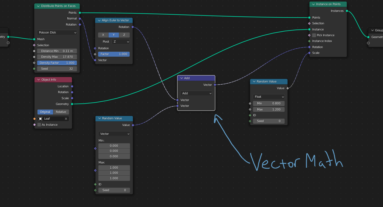
We can use this ‘Random Value’ node to affect the leaf rotations as well. However, in order to not completely override their current rotation, we’ll have to connect the graph in a different way than we did the scale randomness. We need to tell each leaf to get a combination of its current orientation and a random value.
For this, we need a node that can bring those two things together. Since we’re dealing with rotation values (x, y, z), we’ll use a ‘Vector Math’ node. This node expects 3-value inputs like rotation values have. I’ll leave it set to ‘Add’ and plug it into my existing graph so that it’s adding up the original rotation plus the randomized rotation values:
Now it’s helpful to watch your 3d view as you make adjustments to the ‘Min’ and ‘Max’ values of the ‘Random Value’ node for rotation. For my setup, the Min/Max X values affect the ‘pitch’ of each leaf (think about how your head nods up/down), whereas the Y values affect the ‘twist’ or ‘roll’ of each leaf. Last, the Min/Max Z values affect the left/right rotation. You’ll definitely want to tweak these values to your own preference for how your particular leaves should look. Don’t forget to use a reference image if it helps.
I start by setting all the values to zero…
Improving Access to Our Node Graph
It’s great that we have so many parameters we can adjust, but it’s not so great that they’re scattered all over the place. There’s an easy fix for this problem.
All you have to do is click and drag from one of the node inputs back to one of the outputs of the ‘Group Input’ node. Doing so will ‘expose’ that parameter to a slot right on the ‘Geometry Nodes’ modifier itself. After all, it would get tiresome to have to keep opening the graph just to change one number. Check it out:
So you can decide exactly what parameters to expose for this graph to make future adjustments easier. Exposing ‘Seed’ values that randomize stuff is often a good idea. You can even make those exposed parameters get affected by other parameters or variables, but we’ll stop here before this becomes a complete Geometry Nodes tutorial.
Getting Ready for Export
Since ‘Geometry Nodes’ is a modifier, we would normally try to use the ‘Apply’ button to accept all the changes to our object. However, using ‘Apply’ on this particular setup doesn’t work. Go ahead and try it… I’ll wait….
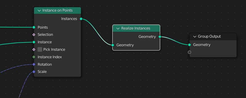
Everything just disappears! Why? Well, remember how we started? This graph exists on the canopy object and all those instanced leaves were never turned into real geometry. There’s a node just for this operation: ‘Realize Instances’. Adding this node to the end of the graph will tell Blender that each of those leaves should get converted into regular mesh objects, then the graph output combines them into one at the end.
Leaf Material
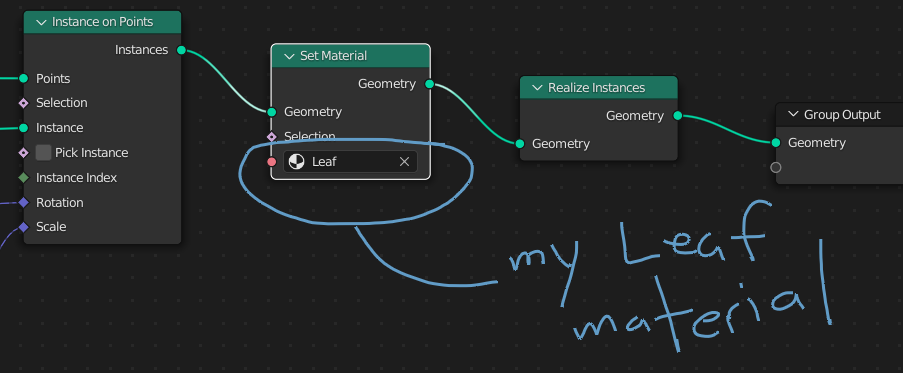
Materials can be a little tricky in Geometry Nodes. Similar problems to the one above can arise when you need instances to have a material. You have a couple options here though–you can apply a material to the original single leaf model first, or you can be more explicit by adding a node called ‘Set Material’ inside this graph. Assuming you’ve already created a leaf material, you will see that material in the node’s dropdown menu. This node should go before your ‘Realize Instances’ node.
Take a Step Back
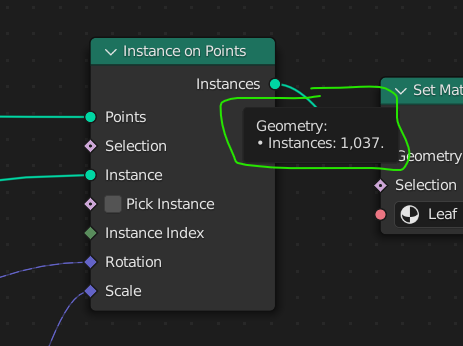
Now is a great time to exhale (and, of course, save) and take a look at your hard work. This single graph with its 9 or 10 nodes can do pretty amazing things. That canopy mesh can change shape and the leaves will still scatter all over it as you designed.
Imagine before you knew about Geometry Nodes–having to update the leaves by hand every time you wanted to make an adjustment!
In fact, you can even put this graph on a different object altogether and get leaves on it. You can even save this graph to be used in other projects!
It’s also a good time to remind yourself that everything is still adjustable at this point. You can play with leaf angles, sizes, and even go back to adjust the geometry of the single leaf if you want more detail. Just remember that any additional faces or vertices will be multiplied by however many leaves you have.
Leaf Texturing
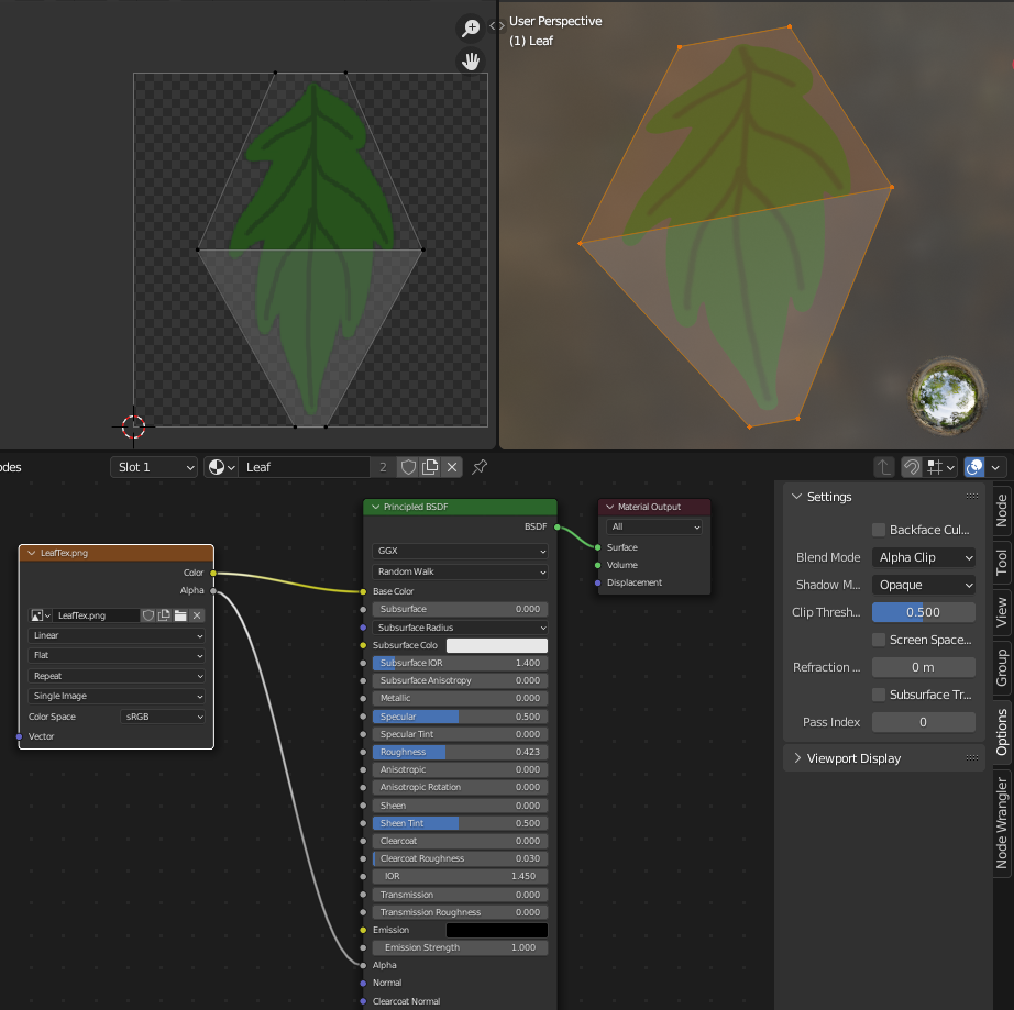
We didn’t really spend much time figuring out how the leaves themselves should look in terms of materials. We didn’t even use a texture for them. But this is an area where you will ultimately need to decide what sort of look you’re going for. Do you want the leaves to be more like fuzzy blobs that help soften the silhouette of the tree? Or perhaps you want each leaf to be more individually recognizable with details on each one. Maybe somewhere in between?
If you’re looking to add a texture to the leaves, chances are you’ll need some sort of alpha transparency. I almost always recommend sticking with the less expensive ‘alpha clip’ to help define the outline of the leaf. Using ‘alpha blend’ transparency is likely to lead to all kinds of visual glitches because of all the overlapping leaves and is best avoided. For a more complete understanding of alpha transparency, you can follow along with this other Creative Labs article.
If you’re going for a more stylized look, you can forgo using leaf shapes altogether in favor of something more abstract. In many cases, you can simply use a single quad plane instead of shaping the geometry into a leaf-like shape. It can be really fun to experiment with different leaf shapes, colors, and styles.
Leaves and Lighting
If there’s any part of this process that’s a bit of a ‘trick’, it’s this part. Now, it’s not completely necessary but it can be useful, especially when going for a more stylized look.
When a tree is viewed from far away, our human perception tends to ‘blur’ things and eliminate details. Impressionist painters use this to great effect, but in computer graphics, sometimes the small details become noisy from afar and can distract from the style you’re trying to recreate.
To help create the illusion that our leaves are more like big clusters, we can do an operation in Blender where we ‘steal’ the surface normal information (aka, the direction of the faces) from the canopy mesh and transfer it to the leaves. There are a few ways, but I like to use the ‘Data Transfer’ modifier.
To start, just like earlier, I like to duplicate the canopy mesh and keep a copy somewhere in case something gets messed up. Then I’ll do an ‘Apply’ to the ‘Geometry Nodes’ modifier which will effectively convert this whole bunch of leaves into a single, regular old mesh. To that, I’ll apply the ‘Data Transfer’ modifier.
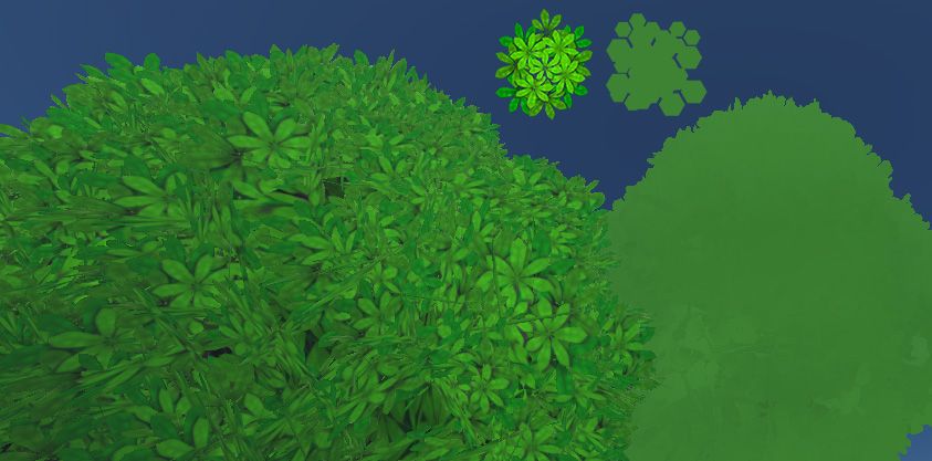
After increasing the density and size of the leaves, it’s a little easier to see the difference transferring the normals makes. If you zoom out further, the effect becomes even more apparent. The canopy of leaves looks more like one form instead of a noisy collection of individual elements.
If we turn the old canopy blob object back on and give it a greenish material with similar roughness to the leaves, the leaf geometry will appear to blend with it much better, especially when viewed from certain angles. Sometimes I give the inner canopy blob mesh a plain color. Other times, I make a texture that looks like a mess of leaves. Every situation is different, so again, I highly encourage you to experiment.
The underside of each leaf isn’t explicit geometry–it’s just the back face of the top of the leaf. As a result, the surface normal under there doesn’t exist so any light hitting the underside just passes through. Unfortunately, since we did the ‘Apply’ operation on our object, we no longer have all that easy editability. But wait–if you saved a copy of the object from an earlier step, it’s not too difficult to add some backfaces to our single leaf and repeat some of the processes afterward.
Just remember that the order of all these operations matters. So now that you have a better understanding of what each step does, you can better decide when to, for example, transfer the surface normals.
Wrapping up
If nothing else, you hopefully have learned how powerful Blender’s Geometry Nodes system can be. Not only can it be used to make complex objects, but it can take complex operations and make them much simpler for you to work with. The best-made graphs are the ones you rarely need to revisit. Procedural systems like this can be used and reused in multiple projects. It’s as simple as using Blender’s ‘Append’ operation and pulling your graph into a new file.
I highly encourage you to discover more about Geometry Nodes by looking at videos and forums where people share their knowledge. While the system is evolving rapidly, making it difficult to create tutorial content that isn’t quickly out-of-date, there is quite a lot of knowledge on the web.
And, as always, you can join us in the Hubs Discord to ask questions and show your progress. I’m sure there are plenty of creators who would love to use any handy graphs you’ve made.